Following is some general information and background on the "anchor hoy".
For information on the first model, built from the Grimwood plan, click here.
For information on the second model, built from plans found in the National Archives and combining reconstruction
done by Grimwood, click here.
In general, a "hoy" is a name for a working boat, often a vessel used in a harbor or port for the various
chores involved in shipping goods and supplying ships. Large sailing ships often anchored some distance off shore,
especially when their draft was greater than the depth of the harbor near inshore or when the depth of water varied
greatly with the tides. These larger ships were serviced by small boats which carried cargo and crew to and from the
vessels and also carried to the ships all the cargo, supplies, provisions, freshwater, and such needed for the
next voyage. The "anchor hoy" was one
example of this type of coastal/harbor craft. This specialty vessel was designed and adapted to carry large anchors or
similar heavy objects from ship to ship or ship to shore and to transport or relocate heavy mooring anchors, often
reused ship anchors,
when they needed to be re-positioned. Also, they were able to recover anchors "lost" in shallow waters, as will be discussed
later.
I first saw mention of an anchor hoy in the book by V.R.Grimwood "American Ship Models and How to Build Them".
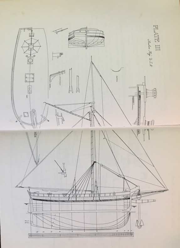
To the left is a picture of the Grimwood book and below is a photo of the plans for an anchor hoy
in the book. I drafted a plan in 1:48 scale based
on this plan and scratch-built a model of the vessel in the latter 1990s. My plan included drawing up the
individual frames including the tapered shaping of the forward frames as I had seen in other plans. Something
I would not bother doing again, as it is easier to cut the frames to the untapered size, frame the hull
using the Hahn technique (see notes on the Raleigh) and taper the frames in situ. That said, if you want to
more accurately model the frames and/or finish the inside of the hull, you will need to taper the inside
of many frames, particularly any cant frames, and that is best done before setting up the frames on the keel.
I now still generally cut the frames slightly oversize and taper the inside at the time I set the frame
up, using a power sander, then once the frames are on the keel, taper the outside of the frames as needed to
get a smooth run for the planking.
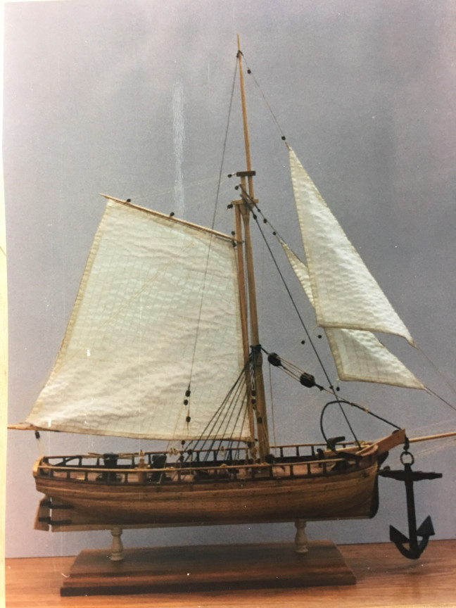
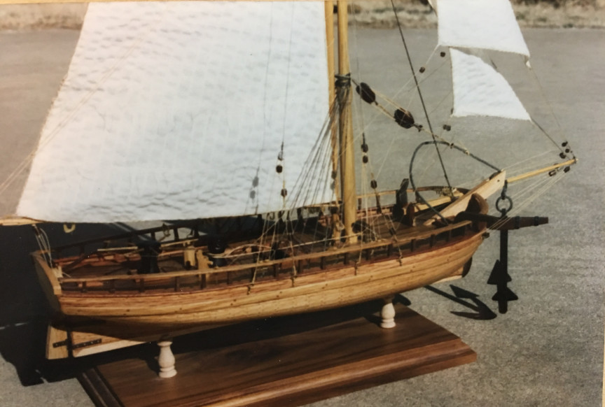
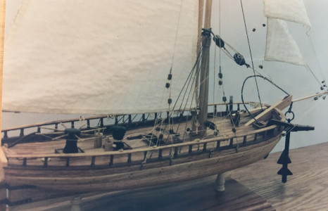
Following are some photos of the first anchor hoy model built over the Grimwood plans.
The model was scratch built in 1:48 scale using afromasia wood for the frames, planking and deck and maple for
deck details. Sails are made from light weight cotton fabric. The rigging was purchased line in
various diameters. The anchor was made from ebony.
It ended up being a fairly interesting model, although the planking was not done accurately, but I
was satisfied with the result. But before too long, I found that an Anchor Hoy is a fairly
common subject for ship modelers as I discovered there are multiple other models made over
the Grimwood plan pictured on the internet.
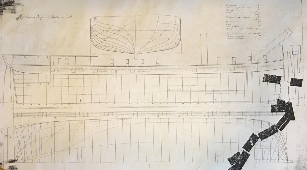
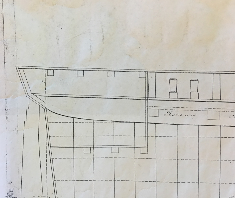
Below are some photos of the plans I found in the National Archives
for an
"anchor hoy". Most of the plans in the Archives are in 1/4" or 1/2" to the foot, so
for this model, I photo-reduced the plan to 3/16" (1:62) scale, as for the last decade
or so I have been building all sailing ship models in the same scale. I do this for
two reasons: first, it makes an easy way to compare the size and construction details
of different vessels - a "light" frigate (Raleigh) versus a "heavy" frigate (Constitution);
and, second, it lets me use fitting on several models. When I make blocks, for example,
or deadeyes, I make a great many of them, to have extra on hand for the next model.
At first, I intended to model this vessel with planking left off part of the deck and hull
to expose the gearing mechanism of the double capstan. But I was unable to find
satisfactory information about how such a geared device would have been constructed
in the early 1800s. I first thought to make up large wooden gears similar to those used
in windmills, but that seemed an older technology, and I found some illustrations
suggesting that by the early 1800s such gears might have been a wooden wheel with a
metal rim, the rim being of cast iron and having the teeth in the casting. In the end, I
could not be certain what the mechanism might have looked like, so I decided to make
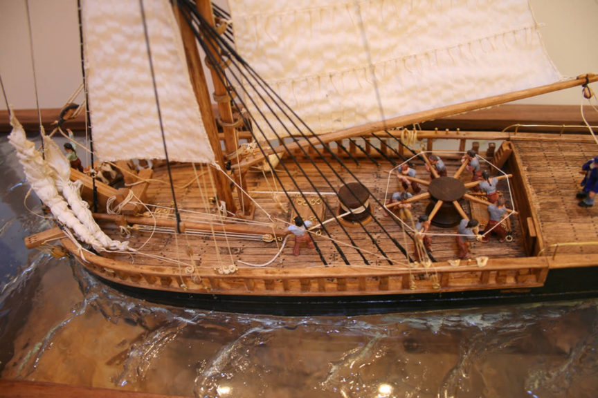
the model as a diorama, with figures on it that would illustrate how the
vessel might have operated. By this time, I had become more interested in how
various tasks were done on a ship and wanted my models to show how things worked as
much as what they might have looked like. So the model developed into a story.
In the story, the vessel is operating in relatively shallow water retrieving an
anchor lost by a larger ship when the anchor flukes became lodged in rocks and
the anchor chain broke. Telling the story required that I understand a bit about
how ships anchored and how an anchor might be retrieved if lost.
When a ship dropped anchor, the anchor had attached to it an "anchor buoy", which was
a length of stout rope, secured at one end to the lower end of the shaft of the anchor, not at
the top ring where the anchor cable itself attached. The other end of the buoy rope
which was somewhat longer than the depth at which the anchor lay, held a wooden float.
This float served two purposes. First, it marked the position of the ship's anchor
for other vessels so they would not drop anchor nearby and foul the two cables or
sail over the anchor cable of the buoyed anchor cutting the cable. And second, the
buoy rope served as a way to retrieve the anchor if it was not possible to bring the
anchor up by pulling on the anchor cable alone. Anchors of the time were designed to bury
one of the flukes into the bottom, and sometimes they lodged so securely, they could
not be brought to the surface by hauling in the anchor cable, as pulling on the top ring
of the anchor might only bury the fluke deeper into the bottom, or lodge it more
tightly in a rocky bottom. The buoy cable, however, was secured to the lower end of the
anchor shaft, so pulling on it would retract the anchor in the opposite direction and
presumably free the fluke lodged in the bottom. If a ship was in a hurry and needed to
leave anchorage quickly, the crew might cut the anchor cable of a stuck anchor, leaving
the buoy to mark the location for retrieval at a later time.
In the "story" of this model, an anchor became lodged in some rocks, and the
anchor chain, broke at a weak link when the crew of the ship began to haul in the cable
when weighing anchor. The anchor hoy crew has arrived on site and hauled the buoy on deck,
run the buoy rope over the heavy davit on the bow, and secured it with a quick release
wooden peg to the end of a large tackle block. The hauling end of this tackle passes up
through a block on the mast, then down to a second large block then back to the
secondary driven geared capstan and around it. The large tackle used to haul the anchor
is secured at its upper end to the mast, which is in turn supported by multiple shrouds,
more and heavier than would be needed for a simple sailing mast. In this case, the mast
does not carry the main sail, which is instead mounted to a try-mast just aft of the
main mast. This arrangement permits the mast itself to function largely as a crane
for the davit tackle, although it does also carry a small topmast.
In this story, once the buoy rope was secured and tensioned slightly with the capstan,
the hoy first sailed a bit in direction opposite to the original position of the ship
that lost the anchor, using that motion to pull on the buoy rope and free the stuck fluke.
Now, the crew has hauled the anchor free of the bottom and is carefully beginning to
haul it up to where it can be secured so the vessel can sail back into the harbor to
carry the anchor to the ship that lost it or to another ship or to use it as a
mooring point.
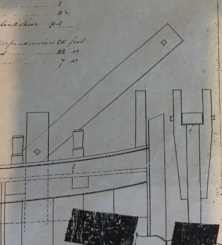
The anchor hoy has several specialized features. Most notable are the extremely heavy
davit at the bow and the double geared capstans. But the vessel also had a retractable
bowsprit and forward rigging and sails that could be moved out of the way when working
on retrieving an anchor. In this particular plan, there was also a large water tank
below the deck. There is no indication the purpose of this tank, which seems too far
forward to act as ballast to counter the weight of an anchor carried on the davit, and
may simply reflect that this particular vessel also was a water hoy, carrying fresh
water out to ships at anchor. If this speculation were correct, however, I should think
the plan would have indicated position of pumps for the water transfer, and there are
none depicted. So it remains a mystery.
The plan from the Archives also does not indicate any information about rigging or sails,
other than location of the mast. Most, perhaps all, plans from this time, even those of
large warships, do not have rigging or sail plans. This was because everybody at a
shipyard "knew" how a ship was rigged. All the designer had to do was indicate the position
of the masts, and the riggers could take it from there. Dimensions of masts and spars
were pretty standardized, and American practices followed by a few years those of the
British shipyards. But the sailing master of a ship could revise the rig, even the placement
or angle of masts, as he wished, based on the actual performance of the vessel. So, for
this model, I based the rigging plan on the Grimwood plans, and modified them as I thought
appropriate and as needed to adapt to the somewhat different hull.
In the above pictures of the plans the first picture is the entire plan, next
a detail of it showing the watertank. Then a detail of the small cabin and of the
anchor davit, which is very different from the one shown on the Grimwood plan.
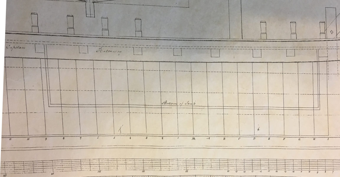
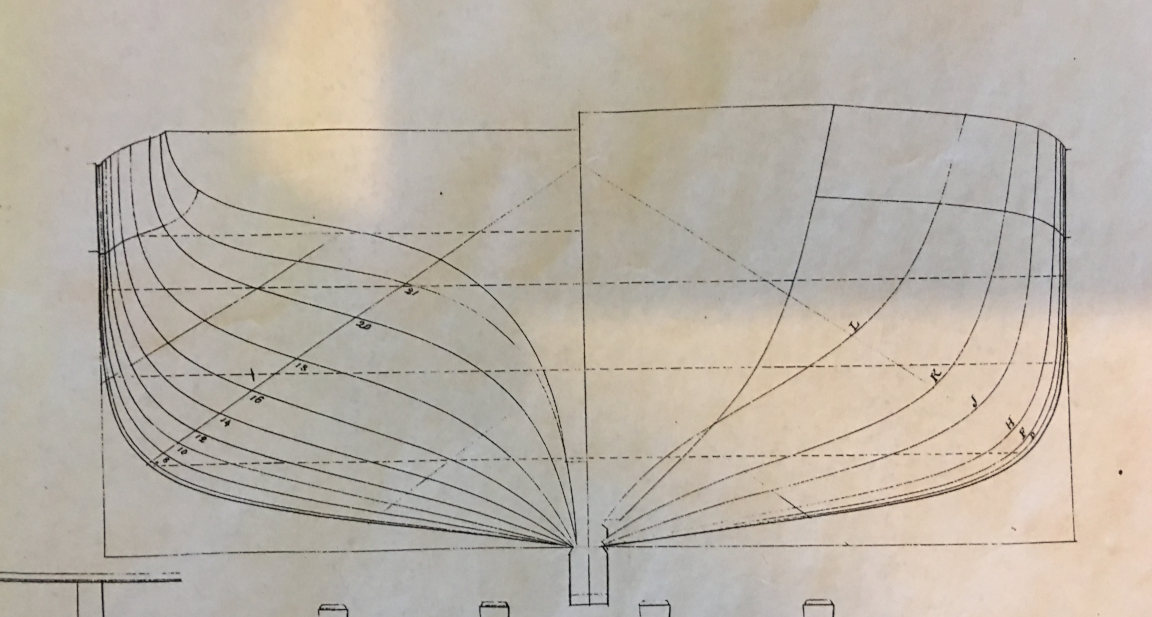
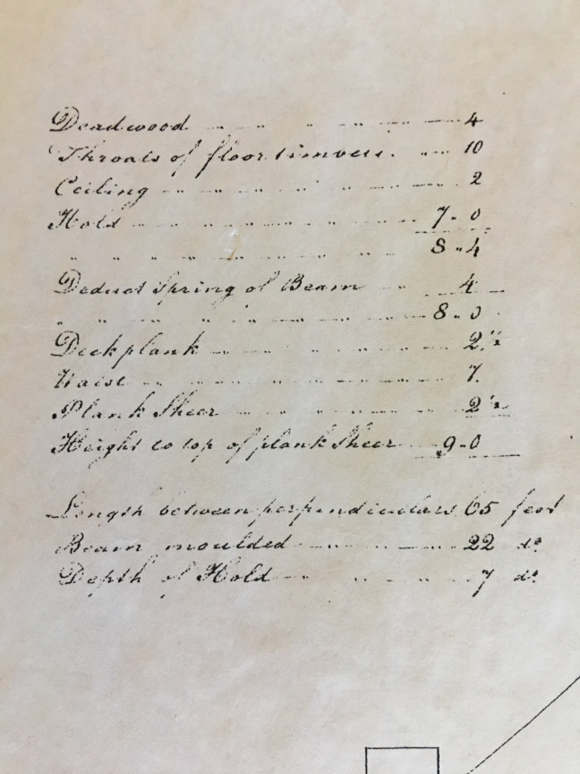
Above on the left is a photo of the plan showing the stations. On the
right is a closer view of the specifications/dimensions of the hull as
shown on the plan.
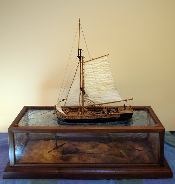
Once I had decided I wanted to make a diorama of the hoy retrieving an
anchor, I needed to decide on the design of the case. First, I planned
a case to hold the hull and model the sea floor. I roughed out the dimensions
for this case and then after I had built the hull I used it as a pattern to
make a cut out in a piece of acrylic sheet to accommodate the hull at about the
waterline. I then completed the model of the vessel and set it aside. Then I
made the large anchor the hoy would be retrieving.
Next I decided on the final dimensions of the two part case. The lower part
modeled the sea and had to be tall enough to allow the anchor to be suspended
above the sea floor, its top would be the acrylic sheet holding the hull,
and the upper part of the case would protect the model itself. I then milled the lumber
to size for the case, cut acrylic glazing for all the sides and ends and trimmed the
sheet I had cut out for the hull to final size.
Once everything had been cut and
trial fitted, I made a bottom for the lower case of plywood, primed it, and used
plaster to model a gently sloping sea floor with rocks here and there, including
some rocks where the anchor had been lodged. I used the anchor and the model
itself placed on the top of the lower case to judge final position for all
components and to model the sea bed. Also, I drilled a hole in the acrylic
holding the hull through which would pass the buoy rope holding the anchor.
The sea floor is painted with water colors and then sealed with a matte
varnish.
The plastic glazing of the sides and ends of the lower case are textured on the
inside with tinted epoxy to create the rippled effect when viewed. I used a
very fine emery paper to rough the acrylic slightly then used a tongue blade
to apply quick setting clear epoxy adhesive to the glazing. I tinted the
epoxy slightly with water borne pigments in shades of light blue and tan and
applied several layers to get the effect I wanted. I have done this a few times
and find that it probably works better if the glazing is installed in the wood
frame before doing this, but is also works fine to do it before assembly as long
as you keep the epoxy back from the edges about a quarter inch.
I used a similar technique to texture the top of the lower case to resemble the
surface of the sea. Again, I used multiple layers of epoxy, some lightly
tinted, some clear. As the epoxy started to set, I modeled the slight waves,
and when it was further hardened, I used toothpicks to make the peaks and
create the slight wake of the boat. Once the sea surface was nearly done,
I installed the model and epoxied it into place, doing further multiple
applications of epoxy and shaping it as above. I then rigged the line to
the anchor and secured it so the anchor hung above the sea floor when the case
is lowered onto and fastened to the base.
Once all that was done, I assembled the upper case and installed it onto
the lower case.
The pictures above show the model installed on the lower case with the upper case
removed.
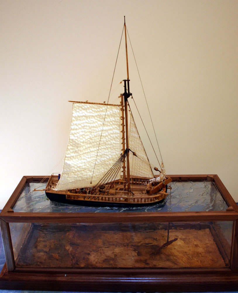
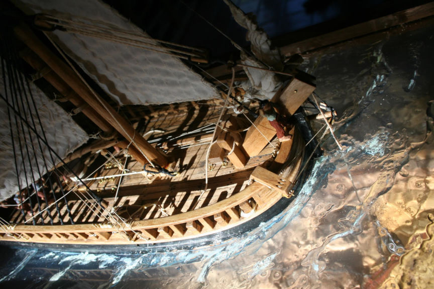
On the left is a picture of the finished model on the base from bow on. You can
see the modeling of the sea surface and also get a sense of how the sea bottom
appears through this surface. As well, you can see the large davit and the buoy
rope to the anchor. The retractible bowsprit, to port of the davit, is withdrawn
using the tacke visible on other views, and forwardmost staysails have been
furled to permit working the davit.
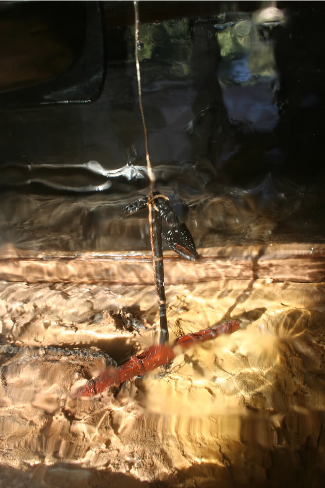
On the left is a picture taken through the side of the lower case
to show how things appear as if under water.
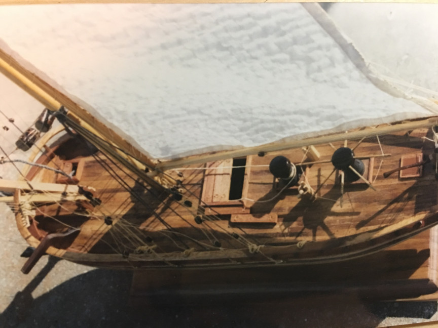
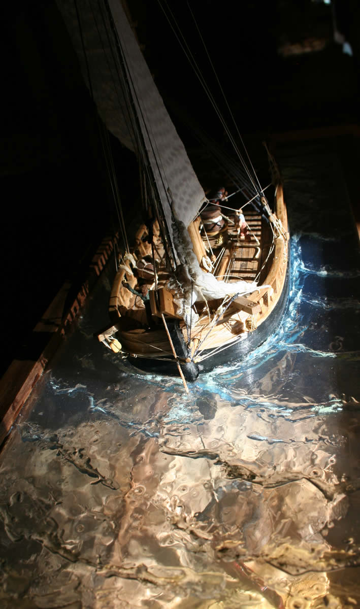
The left hand picture shows the crew at the capstan with the captain at
the tiller. There is an additional crewmember standing on the rail at the bow
beside the davit to signal the capstan crew when to haul the line to further
raise the anchor. An anchor of this size could seriously damage the hull of
this small work boat and great care must have been required to safely handle
an anchor in these circumstances.
On the right is a photo of the starboard side of the anchor davit
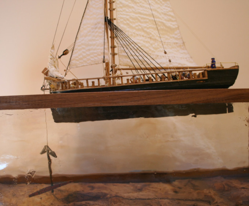
A final picture of the model on the sea. She is bow-down having taken the full weight
of the anchor. In this model, I made an anchor about the size of what a ship of the line
might have carried, perhaps weighing half a ton. Such anchors weighed from hundreds to
thousands of pounds, depending on use. The largest anchors were carried at the bow of
ships and often rigged for emergency release if needed. A merchant ship might carry three
or four anchors, a warship six to eight. The anchor
I made was in the "old admiralty pattern" which was used well into the early 19th century,
although, since anchors were made by many suppliers, patterns and weights varied.